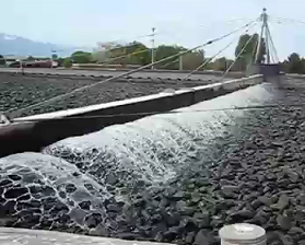
Trickling Filter is the most common choice of use in biological wastewater treatment plant. The filter system is consist of a media bed in which wastewater is continuously distributed. Trickling filters can be divided into different types mainly on the criteria based on the organic loading rates to the treatment plant system from low up to super-high rate trickling filters. Most of the time, two-stage filters are often designed and installed back to back in a series involving two sets of filters.
Low-rate trickling filter is a simple setup that will work in tandem with other device to produce effluent discharge with overall consistent quality. It can only take in wastewater influent with a certain degree of biological load and there is no recirculation of wastewater involved. Design of the filters can either be rectangular or circular in shape and hydraulic loading is controlled using pumps to a small sized dosing tank to achieve a consistent rate. In treatment plants with smaller capacity, extreme care must be applied to ensure that the efficiency of the whole process does not suffer due to long stagnant interval period of 1 to 2 hours. This is important in order to protect the biological slime that can degrade due to lack of moisture.
Low-rate trickling filters are also known to provide highly efficient BOD removal due to the design of the system. In the whole setup, only the top portion of the filter media are filled with biological slime while the lower part are usually populated by nitrifying bacteria. Presence of these bacteria is important in any wastewater system because it helps to oxidize ammonia to nitrite and then nitrate and thus an efficient treatment plant should have a well-established population. However, main disadvantage associated with low-rate trickling filters is the odor problem coming from stale wastewater because of its slower loading rate.
General Process Description
 A conventional trickling filter distributed system is made in such a way that wastewater is sprayed through a rotary distributor arm that consists of a series of nozzles so that the liquid spreads evenly over the surface of the filter media. The rotary and turning force is actually driven by the flow of water exiting through the reduced orifice size and as it comes down, there is a small plate that is located beneath it so that this will allow an even distribution. The solid media is basically made up of rocks or synthetic plastics and as explained earlier, it can be grouped into standard rate, intermediate, high rate or a super high rate system. The arrangement will provide enough surface area for the development of bacteria and biomass that will biodegrade the wastewater as it trickles and flows down the stacked media. Depending on the type of material used and how it is arranged, certain systems will have the stacking extending 3 up to 20 ft in depths.
Associated Operational Problems
The most common operational problems are mostly related to the maintenance aspects. For example, the filter underdrain which is made up of a channel which collects the wastewater and allow proper ventilation to support the growth of biofilm, should never be filled up and exceed more than 50% of its level, or else there will not be enough exchange of gases that will eventually leads to breakdown of the system. The maximum hydraulic and organic loading rate must also be determined so that the trickling filter does not operate beyond its designed capacity. This can be controlled by adjusting the recirculation rate and once the best flow ratio has been determined, it must be maintained throughout in order not to cause overloading. Apart from that, in order to ensure optimal performance, growth of biofilm that sloughs away from the filter media and collects in the underdrain channel should be periodically removed or else, it will cause excessive slime build up that will prevent proper ventilation. Nevertheless, the most important routine checking that should be conducted daily is the BOD testing to see how well the system performs.
A simple calculation to determine the organic and hydraulic loading rate is provided in the equations below:
Hydraulic loading rate expressed in gal/d/ft2 =
Q (gal/d) / Media Top Surface Area (ft2)
Organic loading rate expressed in lb/d/1000 ft3 =
BOD per day (lb/d) / Media Volume (1000 ft3)


